Differentiation and Diagnosis of Sustained Annulus Pressure (SAP) in Oil and Gas Wells
Diagnosing Sustained Annulus Pressure in Mature Wells – Complete Guide

#Keywords: Sustained Annulus Pressure, SAP, Sustained Casing Pressure, SCP, Annular Casing Pressure, ACP, Well Integrity, Oil, Gas, Wells, Brownfields, Mature, Lifecycle, Carbon Capture and Storage, CCS, API, NORSOK, ISO, Diagnosis, Leak, Barrier, Assets
Abstract
Sustained Annulus Pressure (SAP), also referred to as Sustained Casing Pressure (SCP), is one of the most frequently encountered and misunderstood well integrity issues in wells, especially mature and brownfields. Although annulus pressure is commonly observed during production operations, its presence alone does not constitute evidence of barrier failure. The critical engineering challenge lies in distinguishing thermally induced pressure behavior from unintended formation communication. This article presents a structured and behavior-based diagnostic framework for differentiating annulus pressure mechanisms, analyzing pressure rebuild kinetics, and identifying leak paths.
1. Introduction
Annulus pressure monitoring is a fundamental component of well integrity management systems. However, pressure readings without contextual interpretation can lead to incorrect risk classification. Thermally driven expansion of trapped annular fluids can mimic sustained casing pressure behavior. Conversely, small but continuous formation communication may initially present as benign pressure fluctuations but may eventually represent a serious risk. A structured diagnostic methodology based on holistic system behavior, rather than on single pressure values, is therefore required. The objective of this article is to outline such a methodology and reinforce a barrier-focused interpretation philosophy.
2. Classification of Annulus Pressure Mechanisms
Misclassification of thermally induced pressure as SAP may result in unnecessary intervention and cost. Conversely, misclassifying sustained communication as thermal behavior may allow progressive barrier degradation. Common diagnostic errors include reliance on a single test, failure to account for normal temperature fluctuations (e.g., daily operational temperature cycles), ignorance of annulus communication, incomplete documentation, etc.
2.1 Thermally Induced Annulus Pressure
Thermally induced annulus pressure results from the attempted expansion in volume of liquids or gases during heating within a sealed annular space. During production, elevated wellbore temperatures attempt to increase fluid volume; in the absence of volume relief, annulus pressure rises. Upon shut-in and cooling, contraction results in pressure decline. This behavior is directly correlated with thermal effects. Having said this, it does not mean that wells with thermally induced annulus pressures do not require monitoring and possible bleed-off. Such wells may still present well integrity risks, particularly in high- temperature (HT) environments, with the potential to lead to catastrophic barrier failure.
2.2 Operator-Imposed Pressure
Operator-imposed pressure originates from deliberate pressure application during gas lift, injection, testing, or similar operational activities. This pressure source is externally controlled and ceases once surface input stops. Monitoring and documentation are required during the pressure application phase; however, this should not result in sustained integrity concerns once the applied pressure is removed, provided no other annulus pressure source is present.
2.3 Sustained Annulus Pressure (SAP)
Sustained Annulus Pressure (SAP) is defined as annulus pressure that rebuilds after bleed- off and cannot be attributed to applied surface pressure or thermal effects. It indicates an influx from a pressurized formation (hydrocarbon-bearing, water-bearing, biogenic gas, or others) into the annulus through a compromised or failed barrier.
Potential causes include cement micro-annulus and channeling, leakage in completion equipment, casing failure, tubing connection failure, hanger seal leak, etc.
3. Diagnostic Differentiation Methodology
Usually, a single diagnostic test is not sufficient to definitively classify the mechanism causing the annulus pressure. Multiple controlled methods should be applied to evaluate system response.
API identifies the following tests as potential diagnostic methods.
3.1 Shut-In Test
Purpose of the Test
The shut-in test aims to eliminate thermal effects by suspending production or injection. Allowing the wellbore to cool reduces temperature-induced influences and enables a more accurate evaluation of annulus pressure behavior.
Test Procedure
- Record the temperature, tubing and all annulus pressures before shutting in the well.
- Shut-in the well.
- Monitor pressure and temperature trends.
- Record pressure and temperature values during 24 h.
Interpretation
- If pressure does not fall to zero psig, or close to zero psig, after well shut-in, this indicates the presence of a significant leak. Additional diagnostics for Sustained Annulus Pressure (SAP) are required.
- If pressure falls to zero psig after shut-in but rebuilds once the well is returned to service, this indicates pressure communication, most likely due to a small leak. Additional diagnostics for Sustained Annulus Pressure (SAP) are also required.
- If pressure stabilizes at zero psig, or close to zero psig, even after the well is returned to service, this indicates thermally induced annulus pressure. It is required to continue monitoring the well as usual; no immediate integrity failure or action is needed.
Cooling Caution
Cooling following bleed-off may induce vacuum conditions, thereby increasing the risk of corrosion. This should therefore be avoided.
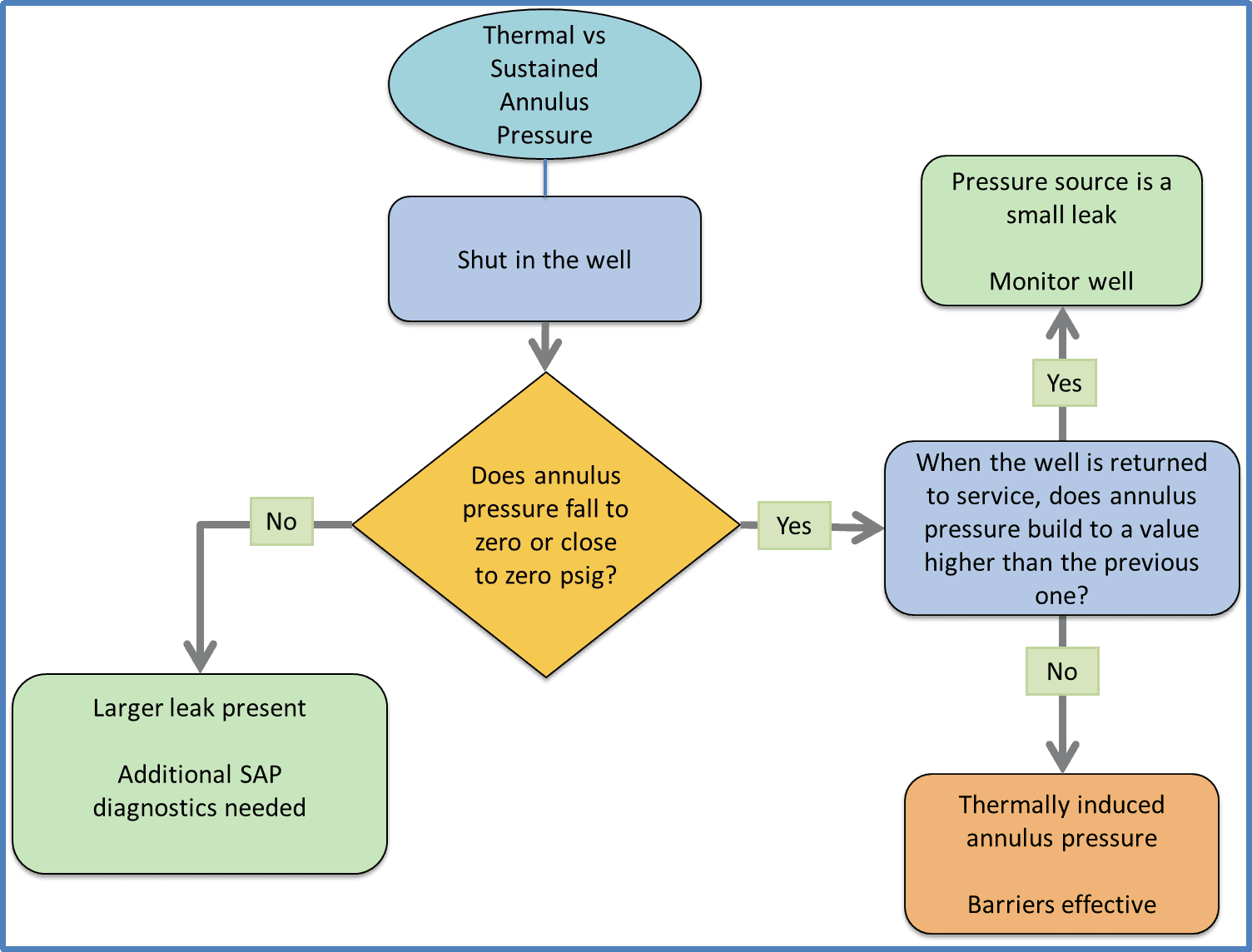
Figure 1. Diagnostic workflow for distinguishing thermally induced annulus pressure from sustained annulus pressure using a shut-in test.
3.2 Production / Injection Rate Sensitivity Test
Purpose of the Test
Modification of the production or injection flow rate is used to determine whether the annulus pressure is thermally induced or attributable to Sustained Annulus Pressure (SAP).
Test Procedure
- Record the temperature, tubing and all annulus pressures before shut-in of the well.
- Modify production or injection rate.
- Monitor pressure and temperature trends.
- Record pressure and temperature values during 24h.
Interpretation
After a change in production or injection rate, assess the annulus casing pressure (ACP) response to differentiate between thermal effects and sustained communication.
- If the annulus pressure stabilizes at the new pressure level generated after the change in flowrate and does not trend back toward its previous value, then this behavior is consistent with thermally induced casing pressure.
- If the annulus pressure trends back toward the pressure level recorded prior to the rate change, reaching the previous value within 24 h then a larger leak is present and additional diagnostics for Sustained Annulus Pressure (SAP) are required.
- If the annulus pressure trends back toward the pressure recorded prior to the rate change but not reaching the previous value within 24 h then most likely a small leak is present and additional diagnostics for Sustained Annulus Pressure (SAP) are required.
- If the annulus pressure shows no response to the rate modification, then this requires further analysis as this is an abnormal annulus behavior.
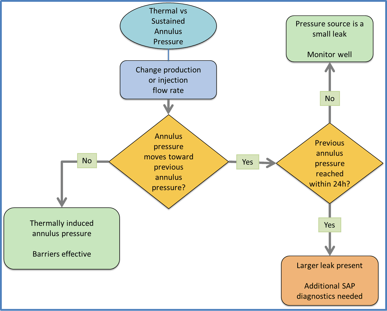
Figure 2. Diagnostic workflow for distinguishing thermally induced annulus pressure from sustained annulus pressure using a change in production or injection flow rate test.
3.3 Partial Bleed-Off Test (10%–20%)
Purpose of the Test
A controlled 10%–20% annulus pressure bleed-off is performed to create a response, allowing evaluation of the annulus pressure without carrying out a full bleed-down.
This method minimizes corrosion risk by avoiding the creation of an annulus vacuum, while providing a preliminary indication of leak rate.
Test Procedure
- Record the temperature, tubing and all annulus pressures before shutting in the well.
- Bleed-off 10%–20% of annulus pressure.
- Monitor pressure and temperature trends.
- Record pressure and temperature values during 24 h.
Interpretation
- If the annulus pressure remains stable at the new reduced level, this suggests either a thermally induced annulus pressure or a very small leak path.
- If the annulus pressure rebuilds to its original pressure value within 24 h then this indicates a large leak.
- If the annulus pressure moves toward the original pressure value but doesn’t reach it within 24 h then this indicates a small leak.
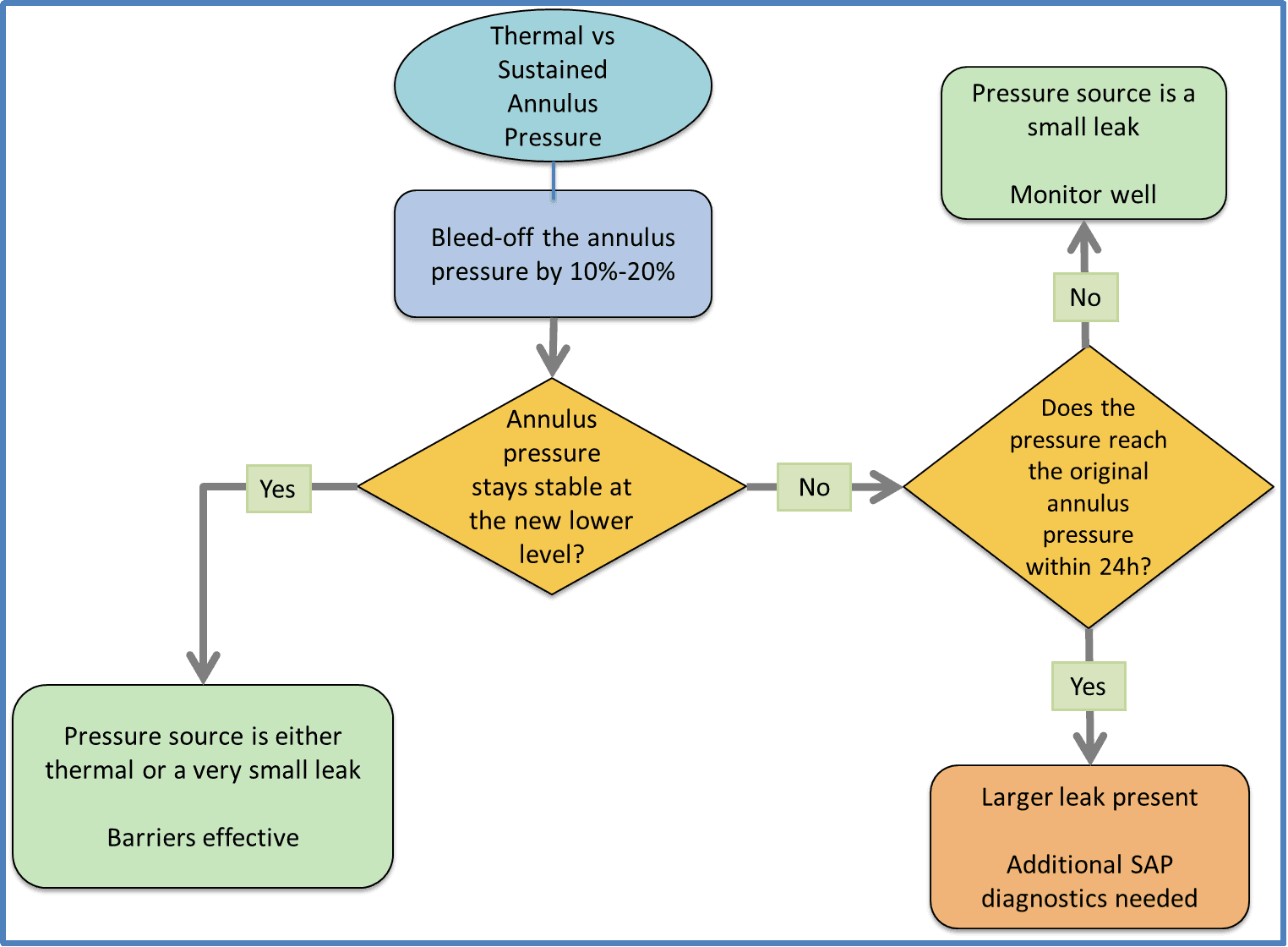
Figure 3. Diagnostic workflow for distinguishing thermally induced annulus pressure from sustained annulus pressure using a partial annulus pressure bleed-off test.
3.4 Full Bleed-Off to Zero
Purpose of the Test
Full annulus pressure bleed-down is used to determine whether the annulus pressure is thermally induced or attributable to Sustained Annulus Pressure (SAP). It is likely the most commonly applied diagnostic method, as it does not require shutting in the well and provides a relatively straightforward indication of the pressure origin.
Test Procedure
- Record the temperature, tubing and all annulus pressures before shutting in the well.
- Bleed the annulus pressure down to 0 psig, or to the lowest pressure practically achievable.
- Monitor pressure and temperature trends.
- Record pressure and temperature values during 24 h.
Interpretation
- If the annulus pressure cannot be bled to zero through a ½’’ needle valve, this suggests strong communication (SAP) as potentially the leak rate is larger than the bleed rate.
- If the annulus pressure rebuilds after being bled down to zero and returns to its original value, or to a lower stabilized pressure within 24 hours, this indicates a small leak path.
- If the annulus pressure does not rebuild to its original value (or to a lower stabilized pressure) within 24 hours after being bled to zero, this indicates either a very small leak path or a thermally induced pressure source.
- A pressure increase exceeding the initial value after annulus bleed-off may occur if the annulus pressure had not stabilized yet at the start of the test, or if the annular hydrostatic fluid was replaced during the test with a lower-density fluid, thereby reducing the hydrostatic head.
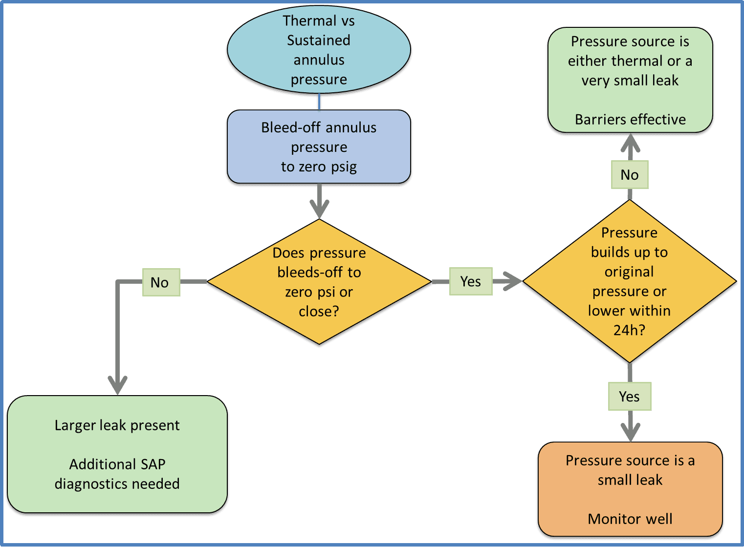
Figure 4. Diagnostic workflow for distinguishing thermally induced annulus pressure from sustained annulus pressure using a full annulus pressure bleed-off test.
Monitoring Duration
Observation time windows must be sufficient to capture the full communication effect. High-permeability pathways may exhibit pressure rebuild within hours, whereas micro-annulus systems may require longer observation periods. The nature and compressibility of the fluid (oil, gas or water) entering the annulus also affect the pressure build-up rate. Although 24h is used here as a duration value, this is only a guideline.
4. Source Identification Following SAP Confirmation
Once sustained communication is indicated, diagnostics shift toward localization of the flow path. Several methods exist; a few are outlined below.
4.1 Tubing Leak Evaluation (SCSSSV and Plugs Isolation)
Closing the SC-SSSV provides mechanical isolation within the tubing string. Valve integrity must be verified first to avoid misinterpretation. If the annulus pressure decreases or ceases to build once the SCSSSV is closed, this indicates that the leak is located above the SC-SSSV.
A more precise tubing leak location can be identified by setting plugs at different depths and bleeding off the pressure above the plug at each interval to observe the response.
4.2 Liquid Level Survey (Echometer)
Fluid level monitoring can help in identifying the depth of leak points (for example, if the liquid level declines until it reaches the leak depth) and in characterizing leak behavior (for example, if the liquid level rises after a bleed-off test, indicating inflow through a leak path).
Having said this, this method is relatively unreliable and is open to interpretation.
4.3 Cased Hole Logging
In cases involving Sustained Casing Pressure (SCP) or suspected barrier failure, cased-hole logging tools provide important downhole diagnostics. Some of these tools are down-hole cameras, noise, corrosion, temperature and ultrasonic logs. These tools could provide precise identification of the depth and characteristics of fluid movement behind the casing.
4.3.1. Temperature and noise Logs
- Temperature Logs
- Usually 25-30 ft area accuracy.
- Easy to interpret.
- Useful for large leaks with low differential pressure (e.g. large holes).
- Noise Logs
- Usually 1-2 inches area accuracy .
- It is useful for small leaks with high differential pressure (e.g. small holes).
- A differential pressure must be established across the suspected leak path.
- These logs allow for flexibility to shut in, flow, or inject in the well. The choice depends on the condition that leads to the most active leak(s).
- If pressure build-up occurs in an outer annulus (e.g. B or C-Annulus), bleeding it off can trigger the desired flow.
- Logging the well with the annulus shut-in at stable pressure and then re-logging with the annulus flowing could provide important information
- The challenge lies in interpreting the data.
- When temperature or noise logs are used, it is good practice to use temperature and noise logs together as each tool has its own advantages and drawbacks.
4.4 Recovered Fluid Analysis
Evaluation of fluids recovered during bleed-off should include chemical characterization and volume quantification. Fluid analysis assists in identifying the origin of the influx, such as reservoir fluids, fluids from shallower formations, injected water or gas, intentionally placed annular fluids, or external contaminants.
The following information should be collected during the bleed-off:
- Annulus pressure immediately before and after bleed-off.
- Total duration of the bleed-off operation.
- Type of fluid produced during the bleed-off.
- Total volume bled-off from the annulus.
- Pressure response in adjacent annuli, to assess possible inter-annular communication.
- Laboratory analysis of recovered fluids, including corrosivity assessment (e.g., elevated iron content, chlorides, etc.) and comparison of composition with drilling fluids used to drill the well.
5. Conclusions
Sustained Annulus Pressure (SAP) remains a technically challenging well integrity condition, not because annulus pressure is rare, but because its interpretation is often oversimplified. Annulus pressure in itself does not equate to barrier failure. The critical task is to distinguish between thermally induced behavior, operator-imposed effects, and true sustained formation communication through a structured, evidence-based diagnostic process.
This article emphasized that reliable differentiation requires a holistic system approach rather than reliance on isolated pressure readings or a single diagnostic test. Shut-in testing, rate sensitivity analysis, partial and full bleed-off evaluations, pressure rebuild speed assessment, cross-annulus monitoring, and integrated downhole diagnostics need to be applied collectively.
Once sustained communication is confirmed, the next step is leak localization. Tubing isolation (where applicable), SCSSSV testing (if available), fluid level surveys, cased-hole logging, and recovered fluid analysis provide complementary diagnostic tools to identify the leak path and assess barrier degradation.
In mature and brownfield assets-and increasingly in Carbon Capture and Storage (CCS) applications-the consequences of misclassification are significant. Over-conservatism leads to unnecessary intervention and cost; underestimation may allow progressive barrier failure and lead to well integrity risks.
Ultimately, SAP diagnosis is not the outcome of a single test, but rather the result of a structured interpretation of the well and annulus response. Sound engineering judgment, supported by integrated data and systematic documentation, remains the foundation of effective well integrity management throughout the well lifecycle.
References
API Recommended Practice 90-2. Annular Casing Pressure Management for Offshore Wells. American Petroleum Institute.
NORSOK Standard D-010. Well Integrity in Drilling and Well Operations. Standards Norway.
ISO 16530-1. Petroleum and Natural Gas Industries — Well Integrity — Part 1: Life Cycle Governance. International Organization for Standardization.