Well Barrier Failure. The Two-Objective Paradigm: How to Assess Failed Barriers and Prioritise the Response
A well barrier failure does not necessarily mean loss of containment or loss of well control. In many cases, one barrier has failed while another continues to contain the well. That distinction changes the engineering question.
Once a barrier failure has been confirmed, attention naturally turns to the failed well barrier element (WBE): what failed, why it failed and how it can be repaired. Those questions matter, but they should not dominate the immediate integrity assessment. The greater concern is often the barrier that is still containing the well. What stands between the source of pressure and further escalation? What barrier remains? Is it genuinely independent of the failed barrier? Can it be verified? What load is it carrying now? And what would happen if it also failed?
The response can therefore be considered in terms of two objectives.These two objectives we are calling them “The Two-Objective Paradigm”.
Objective 1 is to establish a safe and controlled state: understand the failure, maintain containment, verify the remaining barrier and determine the safest operating condition.
Objective 2 is to restore barrier redundancy: reinstate the failed barrier or establish an acceptable alternative so that the degraded condition does not become normalised.
The Well Barrier Failure Response Framework in Figure 1 summarises the progression from anomaly detection to verified restoration.
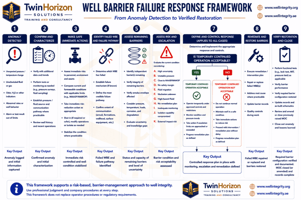
Figure 1 – Well Barrier Failure Response Framework: from anomaly detection to verified barrier restoration.
These nine steps provide a practical workflow, but the engineering decisions within that workflow ultimately revolve around four questions: what failed, what remains, can the remaining barrier be verified, and what response minimises the risk of escalation while the required barrier configuration is restored?
What Is a Well Barrier Failure?
A well barrier is an envelope formed by one or more WBEs that together prevent unintended flow. The integrity question therefore concerns the barrier function and status, not simply whether an individual component is installed.
Failure of one WBE does not automatically mean complete loss of containment. Another barrier may still be performing the required containment function. However, the well may have lost the redundancy intended in its barrier philosophy, increasing its dependence on the remaining barrier.
Terminology matters when assessing this condition. A failed WBE has sufficient evidence that it cannot perform its required barrier to function or satisfy its defined acceptance criteria. A degraded or compromised WBE may retain pressure-containing capability, but its condition, reliability or safety margin has been adversely affected. An unverified barrier has insufficient evidence to demonstrate that it currently satisfies the required acceptance criteria.
A not verified WBE does not automatically mean failed, but it should not be credited as verified integrity. Once one barrier has failed, this distinction becomes particularly important because continued containment may depend on the remaining barrier.
- Objective 1: Diagnose the Failure Before Planning the Repair
Establishing a safe and controlled state starts with understanding what has actually failed. Barrier problems frequently present as anomalies rather than obvious component failures.
Abnormal annulus pressure, pressure rebuilding after bleed-down, unexpected communication, external leakage or failure of a pressure, leak or function test may indicate an integrity problem. The observed symptom, however, does not necessarily identify the failed WBE.
A useful diagnostic distinction is to separate three questions: where is the symptom observed, where does the pressure or fluid originate, and what physical pathway connects the source to the symptom? Confusing these can lead directly to unnecessary or ineffective intervention.
Pressure behaviour can provide important evidence. The assessment may consider whether pressure rebuilds following bleed-down, whether the rebuild rate is changing, whether pressure stabilises, how it responds to tubing pressure or production changes, and whether communication between pressure annuli is developing. Appropriate diagnostics can then be selected according to the suspected mechanism and well configuration.
Field Case: The “Tubing Leak” That Wasn’t
In one field case, abnormal A-annulus pressure initially suggested tubing-to-annulus communication and a possible tubing leak. The diagnostic evidence, however, did not support that conclusion.
Noise and temperature logging found no evidence of a tubing leak, while plugs were set and pressure-tested to confirm that the tubing was sound. Historical cement logs indicated concerns with cement integrity and channeling. Communication within the annulus was identified, and pressure was also present in the casing-hanger void.
Taken together, the evidence pointed to a failure pathway involving cement channeling and leakage at the casing hanger rather than a tubing leak. Had the initial diagnosis been accepted without sufficient investigation, perfectly good tubing could have been pulled without correcting the actual integrity problem.
The case demonstrates why the location at which pressure is observed should not automatically be treated as the location of the barrier failure. Correct remediation depends on sufficiently understanding the pressure source and failure pathway before selecting the solution.
Assess the Remaining Barrier
Once the failed barrier and credible pathway have been identified, attention should shift towards the remaining containment system. The assessment now needs to establish what is containing the well, whether that barrier is really independent of the failed barrier, and what evidence demonstrates that it can continue performing its required function.
Where one barrier has failed, the remaining barrier should, where practicable, be verified. A remaining barrier can be considered verified when there is sufficient objective evidence to demonstrate that it is currently performing the barrier function required of it under the conditions to which it is exposed.
The strength of that evidence should be proportionate to the consequence, uncertainty and risk associated with continued reliance on the barrier. Where practicable, direct verification provides the strongest evidence and may involve an appropriate positive pressure, inflow, or function tests, depending on the WBE and well condition.
Where direct testing is not practicable without additional risk, verification may require a combination of evidence. This could include a recent successful test, stable pressure behaviour, diagnostics consistent with isolation, known equipment condition and confidence that the identified failure mechanism does not involve the remaining barrier.
Stable pressure can provide useful supporting evidence, but it is not, by itself, proof of integrity. Similarly, a historical successful test may remain relevant, but its evidential value reduces as time passes or operating conditions change.
The assessment should also consider whether the remaining barrier is genuinely independent or whether the mechanism that affected the failed barrier could credibly challenge it as well. Two barriers appearing separately on a schematic is not, by itself, sufficient evidence of functional independence.
Assess the Load on the Remaining Barrier
Verification alone is not sufficient. The remaining barrier must also be capable of performing its function under the new load case created by the failure and by the proposed response.
Loss of one barrier can change pressure exposure and differential pressure across the remaining containment system. Looking only at MAASP or MAWOP can therefore give an incomplete picture.
Depending on the well and failure mechanism, the assessment may need to consider:
- load on the remaining verified barrier;
- leak rate and trend;
- margin to MAASP/MAWOP and applicable equipment ratings or operating limits;
- wellhead, tree, tubing and casing status;
- known equipment degradation, including relevant corrosion or erosion;
- the pressure source and whether communication is stable, pressure-limited or continuously supported;
- the ability to monitor and intervene; and
- the consequence if the remaining barrier fails.
The significance of a barrier failure therefore depends not only on the probability of further deterioration, but also on the consequence of losing the remaining containment.
Establish a Safe State, Then Restore Redundancy
Once the failure has been characterised and the remaining barrier assessed, the immediate decision is how to maintain the safest possible condition while redundancy is restored.
Depending on the failure mechanism and resulting load cases, that condition might be shut-in, restricted operation or, in exceptional circumstances, temporary continued production. The purpose is to maintain containment and prevent escalation; achieving this first objective does not mean that the failed barrier has been restored or that the degraded barrier configuration has become acceptable as a normal operating condition.
Temporary Operation While Barrier Redundancy Is Being Restored
Shutting in may be the appropriate response to many barrier failures, but it should not automatically be assumed to create the safest integrity condition. The resulting load case needs to be considered.
Shutting in a producing well can increase tubing pressure. Depending on the leak pathway, this may increase differential pressure across the failed WBE, annulus pressure or loading on the remaining barrier. Continued production can create the opposite problem in other circumstances by increasing communication, leak rate or annulus pressure.
The assessment should therefore compare the relevant flowing and shut-in conditions. Where continued production results in a more favourable load case, with lower pressure, leak rate or annulus pressure and greater margin to applicable limits, it may present a lower integrity risk than shut-in, provided the remaining barrier is adequately verified and the decision is supported by a well-specific risk assessment and applicable requirements.
Where production increases loading, leakage or the threat to the remaining barrier, shut-in may represent the safer condition. Production or economic benefit should not, by itself, determine this decision.
The purpose of the comparison is not to establish that operating on one barrier is acceptable as a normal condition. It is to determine the safest immediate condition while the lost barrier redundancy is being restored.
If temporary continued operation is justified, the assumptions, evidence, operating limits and risk controls supporting that decision must remain valid. An MOC or dispensation/deviation might need to be issued. Reduced confidence in the remaining barrier, failed verification, worsening pressure or leak behaviour, reduced operating margin, new diagnostic information, deterioration in monitoring capability or an increase in the consequence of further failure should trigger reassessment. The trigger for withdrawing temporary operation is not necessarily loss of containment. Action should be taken when the technical basis for continued operation is no longer valid, rather than waiting for the remaining barrier to fail.
Repeated deferral of restoration should also be challenged. The degraded condition is being managed until the required barrier configuration is restored; Operating with a degraded barrier indefinitely is not the solution itself.
Monitoring Is a Control, Not a Barrier
Enhanced monitoring can be important while redundancy is being restored. It can detect pressure changes, establish trends, provide warning of deterioration and trigger escalation actions, but it does not physically prevent flow.
Alarms, surveillance, pressure recording, inspections, operating restrictions and management oversight are controls. They do not replace the missing WBE. A stable and closely monitored well therefore remains a well with degraded barrier redundancy until the required barrier configuration has been restored.
- Objective 2: Restoring the Required Barrier Configuration
Once the well has been stabilised, the focus shifts to the second objective: restoring the required barrier configuration. The failed barrier should be restored or an acceptable alternative established in accordance with the applicable barrier philosophy, operator requirements and regulatory framework.
Temporary acceptance is a risk-management decision; barrier restoration is an integrity-management requirement.
This principle is reflected in well-integrity standards and regulatory frameworks such as NORSOK D-010.
Restoration can itself create difficult intervention problems. In some cases, barriers are required before the intervention can be rigged up safely, while access through the intervention is needed to establish those barriers. Equipment through which access is required may itself form part of the barrier configuration that cannot be relied upon. These situations require well-specific engineering rather than a universal intervention sequence.
In exceptional circumstances, wellhead freezing may be considered as a temporary isolation technique where conventional methods of establishing the required barrier configuration are not practicable. Such applications require again well-specific engineering, appropriate procedures and detailed risk assessment. The practical application and limitations of wellhead freezing in difficult restoration scenarios are covered in our Well Integrity in Mature Fields course.
Closing the Barrier Failure
Completing an intervention does not by itself demonstrate restoration. The relevant question is whether the required barrier envelope is once again providing the required isolation.
A sound closure assessment should establish that:
- the repaired or replaced WBE satisfies the appropriate verification criteria;
- the required barrier envelope performs as intended and it has been restored;
- the original anomaly has been satisfactorily resolved;
- post-restoration behaviour is stable; and
- the barrier status, verification evidence and applicable integrity documentation have been completed.
A successfully tested component inside an otherwise compromised barrier envelope does not restore the barrier. Similarly, if the repaired component passes its test but the original sustained annulus pressure, communication, leakage or other anomaly remains unexplained, the intervention may have been completed successfully while the integrity issue remains unresolved.
Complete certainty regarding the root cause is not always necessary for closure. However, sufficient evidence should exist to demonstrate that the integrity issue has been resolved, the required barrier function has been restored, and the original anomaly has been satisfactorily addressed.
Common Mistakes When Assessing a Well Barrier Failure
Several errors can undermine an otherwise sound integrity assessment:
- Focusing on the failed barrier. Once redundancy is lost, the remaining containment becomes central to the risk.
- Assuming the symptom identifies the failure. Symptom location, pressure source and failure pathway may be different.
- Relying on an unverified barrier. Insufficient evidence of failure is not verification of integrity.
- Assuming shut-in is automatically safest. The resulting load cases should be compared.
- Looking only at MAASP or MAWOP. The complete load case and capability of the remaining barrier also matter.
- Treating monitoring as a barrier. Monitoring controls risk; it does not restore containment or WBE.
- Repairing before diagnosing. The wrong intervention can leave the actual integrity problem unresolved or even in a worse condition.
Conclusion
A well barrier failure should not be assessed solely by examining the component that failed. Once redundancy has been lost, the immediate concern is the barrier still containing the well: whether it can be verified, whether it remains genuinely independent, and whether it can withstand the loads created by the failure and the selected operating condition.
The response has two objectives. First, establish a safe and controlled state. Second, restore the required barrier redundancy and verify that the barrier function has actually been restored.
A temporarily stable degraded well is not the final objective. The required barrier configuration must be restored and demonstrated suitable for the intended operating envelope.
Where a barrier failure requires independent diagnosis, integrity assessment or restoration planning, TwinHorizon’s well integrity services support operators with well integrity assessments, audits and integrity engineering. Related barrier-management principles are also covered through our specialist technical training programmes.